How to differentiate the symbols of a NPN and PNP transistor?
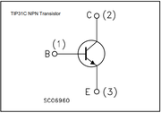
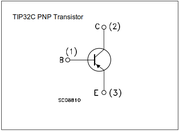
If you've ever been confused about the conventions of the arrows of a BJT symbol, fret not cause this post aims to clarify that doubt. The arrows are used to mark the flow of conventional current through the BJT. For the NPN transitor, electrons flow from the N side to the P side, or from the Emitter to the Base, resulting in the arrow pointing from the Base to the Emitter. In the case of the PNP transistor, electroncs flow from the Base to the Emitter and therefore the arrow points from the Emitter to the Base.
A BJT has 4 regions or modes of operation, namely Active, Reverse, Saturation and Cutoff. Each region depends on the voltage bias applied to Base, Collector and Emitter of the BJT. Below is a table which nicely summiaries the different modes of operation for both NPN and PNP transistors.
| Voltage relations | NPN Mode | PNP Mode |
|---|---|---|
| V E < V B < V C | Active | Reverse |
| V E < V B > V C | Saturation | Cut-off |
| V E > V B < V C | Cutoff | Saturation |
| V E > V B > V C | Reverse | Active |
Happy Hacking!

